CAD Conversions to Render Styles - One Mesh, Multiple Deliverables
CAD Import to Render
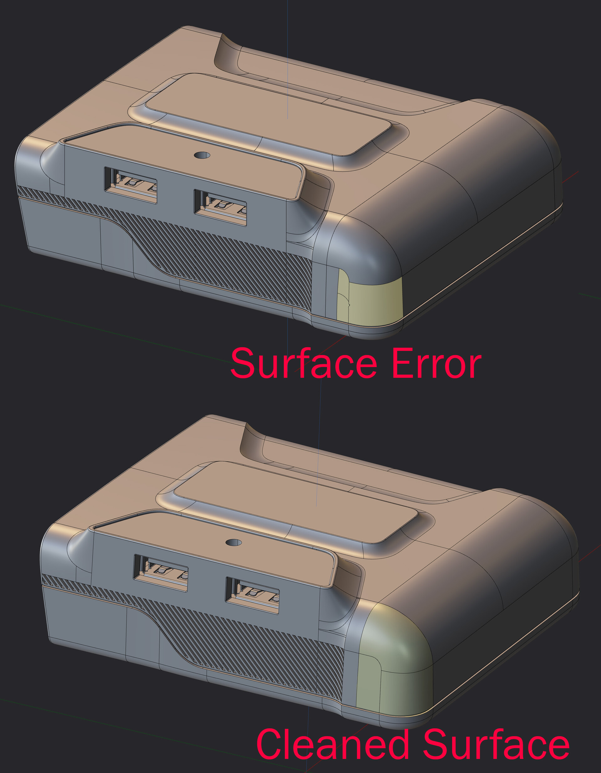
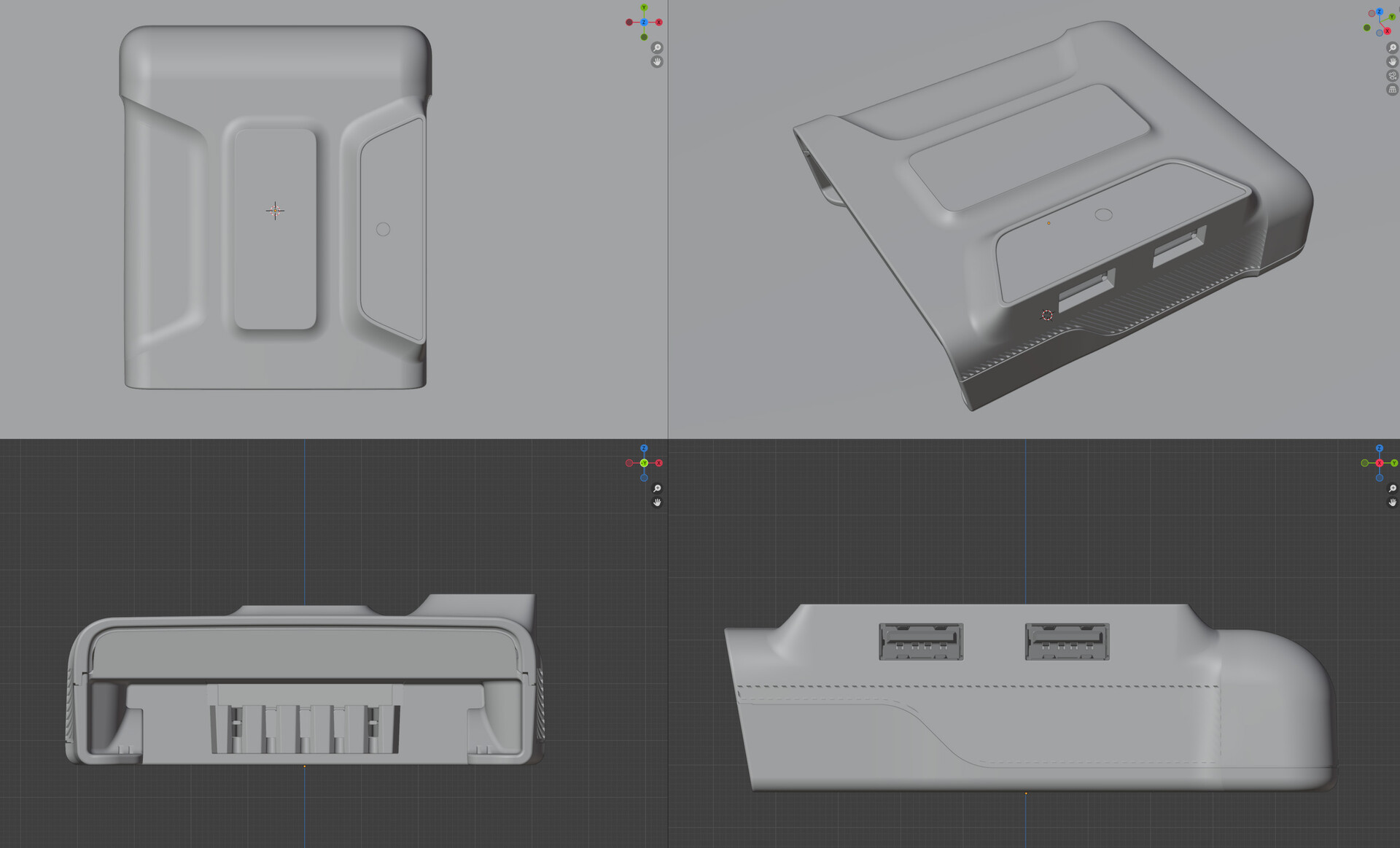
The primary goal when importing CAD data for product rendering is validating the accuracy of the model before any materials or lighting work begins. Some CAD assemblies import cleanly via .STP files with no issues whatsoever, while others arrive with surface problems that need to be addressed before the project can move forward. Topology is always a consideration, but the more critical elements are the surface design features and contours: these define the product's character and need to read accurately in the final renders.
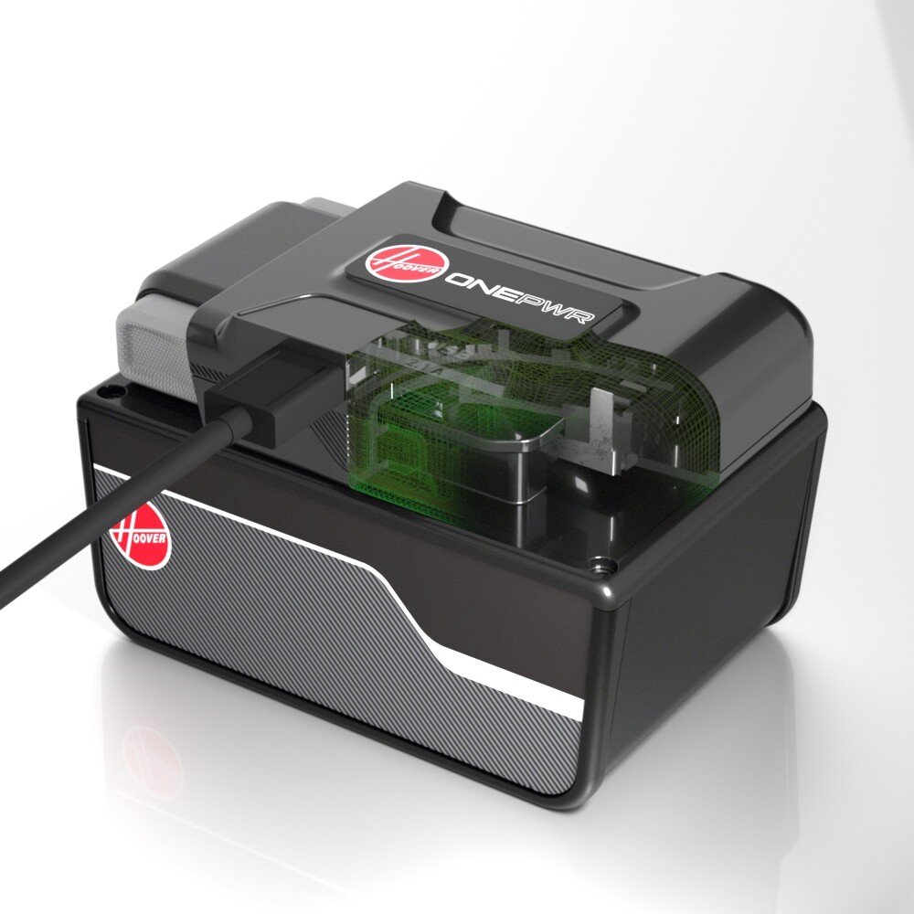
The product featured here is a portable power plate that allows users to draw from their existing battery systems to charge phones and electronics during travel or in emergency situations where standard power access is unavailable.
Once the cleanup pass is complete and all visual artifacts and surface errors are resolved, the CAD model is exported into the destination software for lighting, materials, and rendering. In this case, Blender was used for the project, though Maya with a Redshift renderer is another strong option depending on the client's pipeline preferences and specific deliverable requirements. Once imported, the model is placed on a ground plane and set up in a standard white cyc environment with controlled studio lighting and a lightly reflective floor surface. The final render treatment is determined during post-compositing, but the studio environment serves as the typical default starting point, with custom lighting rigs added as needed to reveal surface shape, material quality, and product detail.
Once the mesh is organized with the scene hierarchy established and any rigging for animation configured, the materials are applied. This step involves processing the CMF document (Color, Material, Finish) to translate the real-world material specifications into accurate 3D shader definitions. Branding and label artwork, provided as vector files, are converted into high-resolution texture maps and projected onto the appropriate geometry surfaces. A key advantage of this layered approach is that label artwork can be rendered as a separate pass in the final composite, giving the team the flexibility to make branding updates or swap out label designs without requiring a full re-render of the entire 3D scene.
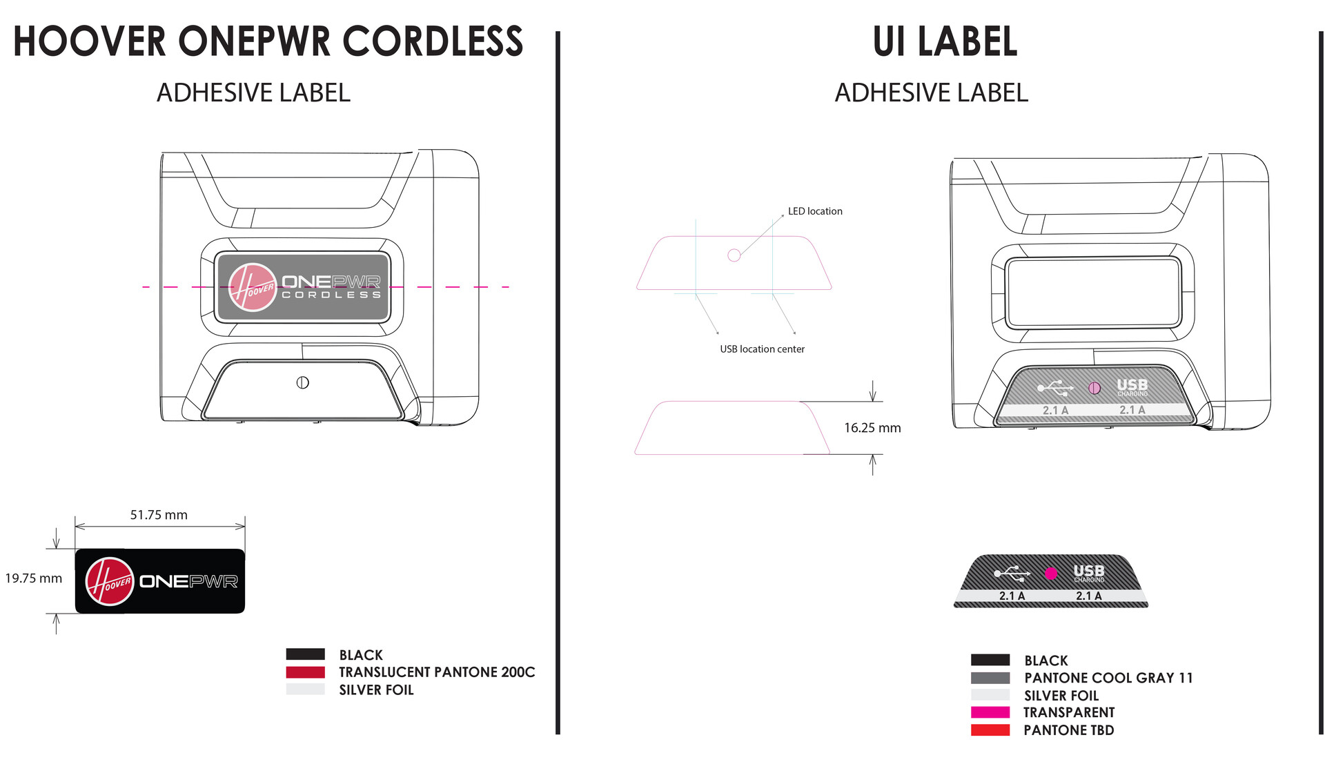
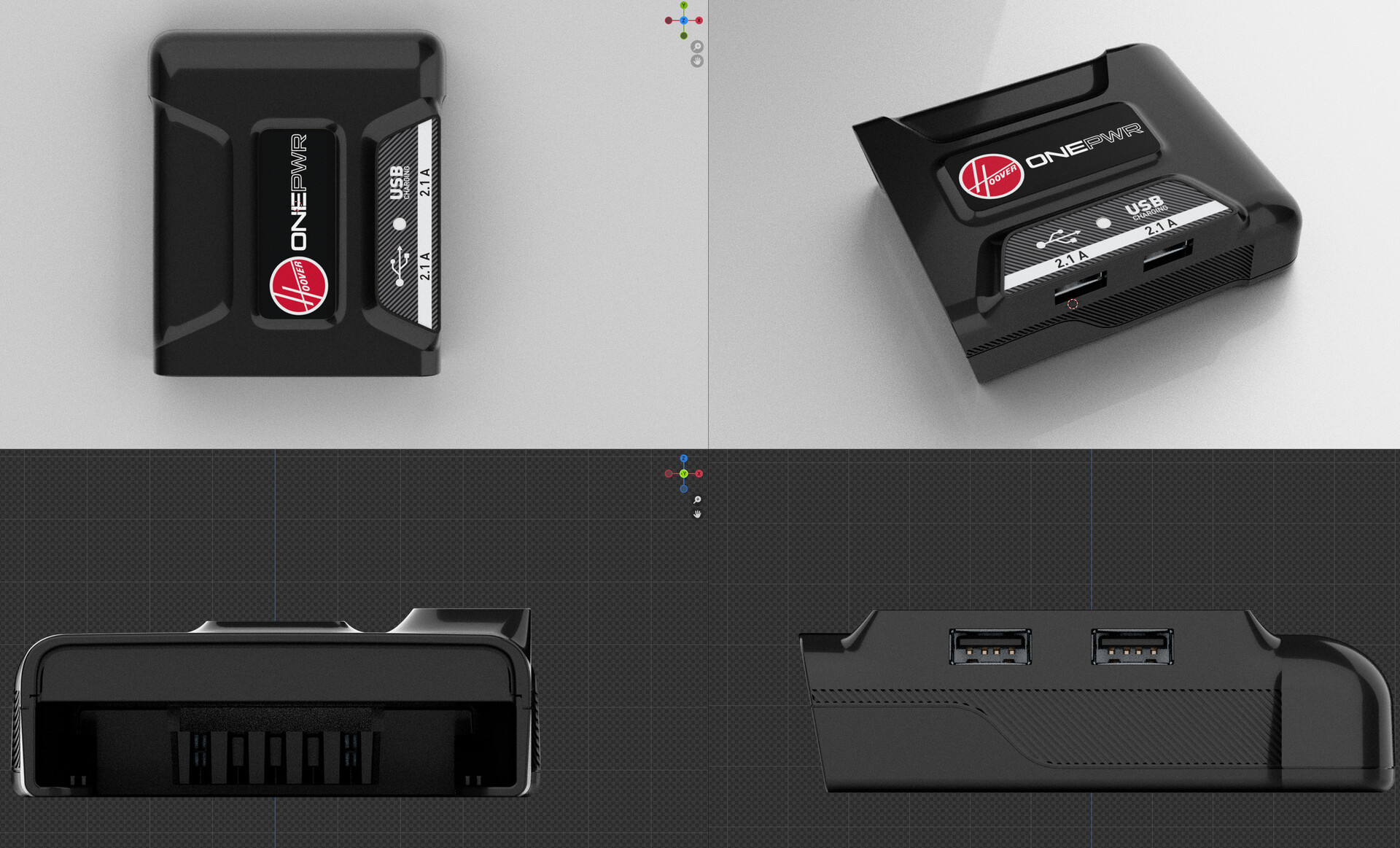
The vector and graphics files are converted into texture maps, applied to the scene, and then the final camera angles and output configurations are established for render. 3D viewport proofs are provided at this stage for client approval, allowing the team to confirm that materials and branding accurately match the physical product before committing to full render time.
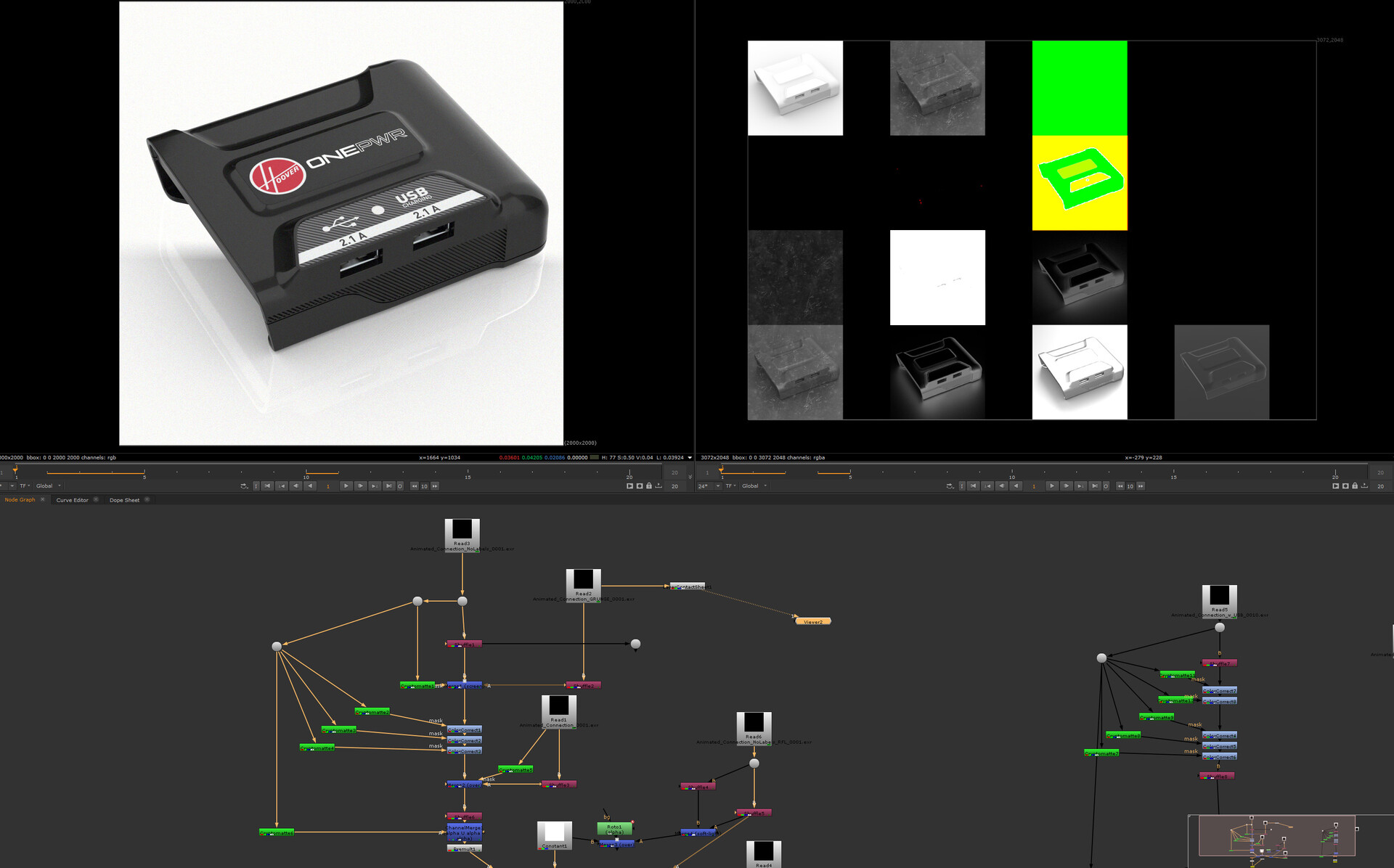
Multi-pass renders covering a range of camera angles are produced, along with usage scenario clips as video assets to place the product in functional context.
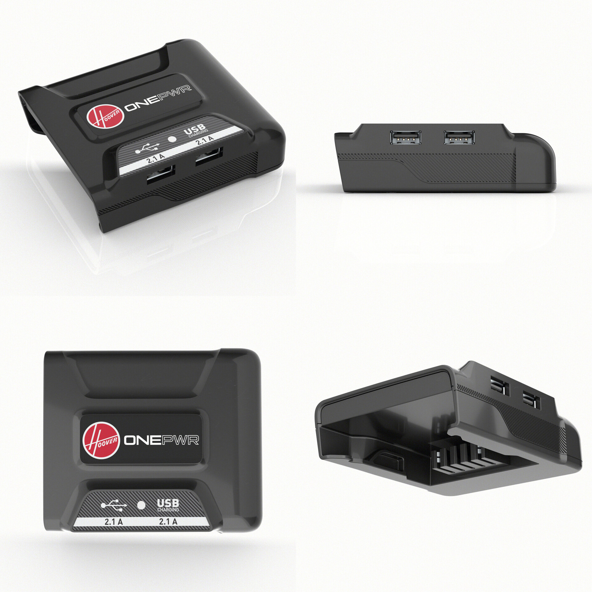
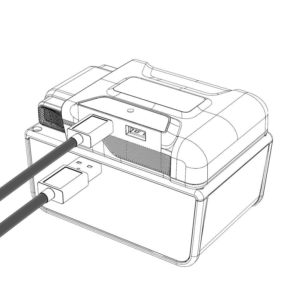
With the 3D scene, materials, and lighting locked, alternate render styles can be generated efficiently from the same master setup. These include technical art cutaways to expose internal components or illustrate how the product functions, as well as clean trace outline renders for use in product labeling, instruction manuals, or technical documentation packages.